

 MagnaboscoCompany is proud to introduce the steam boilers GVR series, representing the best concept of quality, compactness and Energy saving and offering the following advantages: totally pre-assembled, quick steam production and simple working, reduction of maintenance times, maximum thermal output, excellent fuel saving, high steam reserve, use of ”fossil free” fuels too. Thanks to the overheating steam in the accumulator, boilers satisfy any sudden and/or discontinuous need of dry steam at relevant distances too without any problems. The use of any burner’s brand and fuel type allows a rapid after-sale service all over the world. With the introduction of new GVR C equipped with water tank made of painted steel placed under the boiler, reducing in this way the overall dimensions in comparison with the traditional GVR, already compact. All C models are available in their traditional version, which today is called S. In this case the boiler is mounted, as usual, on palletizing base, where the stainless steel water tank, the pump and all other fittings are placed too.
Automatic pressurized
Steam Boiler generators
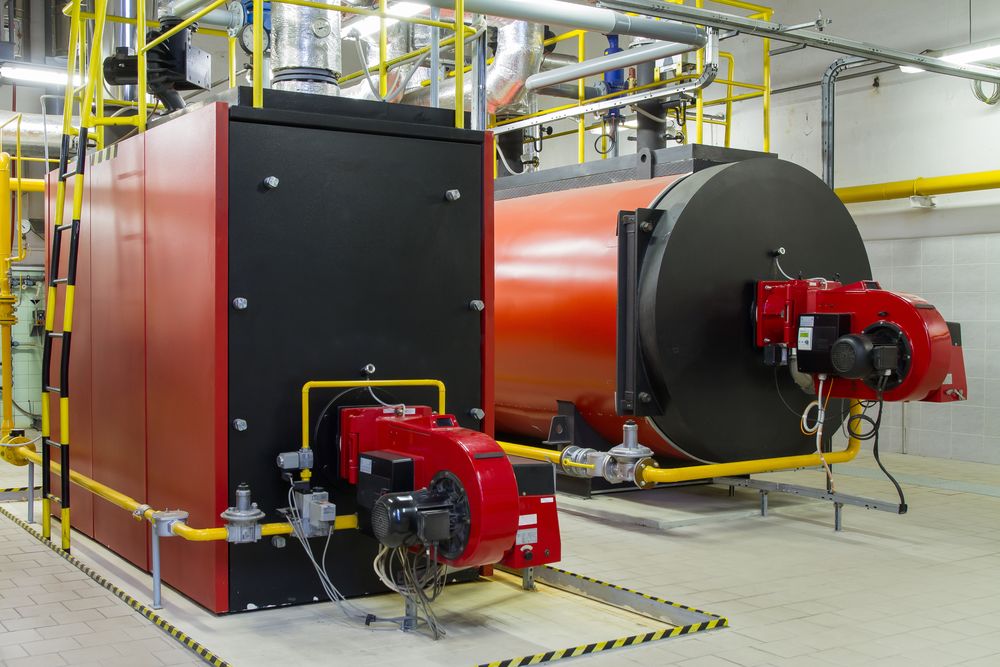
 The steam generators manufactured byArturo Mazzi & F.都是免除专利斯托克一个吗d are supplied already assembled on the platform in stainless steel, equipped with everything you need for them to operate automatically. The range of thermal power is from 50 to 1200 kg/h of steam at pressure of 5 bar (for models up to 350 kg/h) and 12 bar for the larger models. The structural features of the steam generators make them very reliable, simple to use and economical in fuel consumption as they have a very high thermal efficiency, up to 93/94%. On request it is possible to purchase a suitable burner for each model, the ion-exchange water softener and also various options that can optimize the use of the generator and provide better performance and greater durability.
Thermal plants
 Since its origin in 1929,Mingazzinihas always been dedicated to the manufacturing of more and more powerful boilers, up to the realization of today’s thermal plants, for industrial productions on a wide scale. Nowadays it manufactures steam (saturated and superheated) boilers, hot and superheated water boilers and heat generators studied in the minimum details and designed on the measure for the specific needs of industrials: from single units to key-in-your-hands boiler rooms. Product range includes waste heat recovery boilers (WHRB) downward cogeneration and process plants.
Industrial boilers, at the heart of food processing plants
Industrial food processes applying heat at one or more stages are the vast majority: heat is still one of the most widespread means to reduce or virtually eliminate microbiological risk in food. Furthermore, heat is needed to cook food and thus to render it softer, smoother, more digestible and in general more appetizing. Heat is also needed for many other operations, as sanitation of packaging at pre-filling stage, pasteurization or sterilization of packaged food, cleaning and sanitation procedures of equipments, surfaces and food plant in general. Heat is often delivered via hot water, usually produced by boilers. Boilers are two-phase-flow heat exchange equipments: on one side is a boiling fluid, on the other side is either a single-phase or two-phase flow. If the equipment is such to provoke water phase change from liquid to vapor in a controlled and continuous way, it is also defined as “steam generator”. Hot water/steam produced by boilers is usually forced into heat exchangers, devices in which heat is transferred from a hot fluid to a cold fluid/mass commonly through a thin separating wall that can take on a wide variety of geometries: metal structures as pipes (shell and tube, multitube, double pipe or pipe-in-pipe exchangers, etc.) or plates (gasketed plates or matrix and plate fin-tube exchangers, etc.), in order to indirectly contact the food/beverage and transfer heat to it. Less commonly the heat exchange is not through a metal wall and there is direct contact between hot water/steam and food/liquid, i.e. uperization processes for milk treatment. In this particular example, heated water quality must be food grade; in all other cases (no direct food/beverage contact), feed-water microbiological quality is not paramount but other parameters are, as mineral content, in order to prevent fouling. Fouling is the accumulation of undesirable substances on a surface, and can rapidly diminish heat exchange efficiency and increased pressure drop in boiler equipments, especially in presence of an high surface area to water quantity ratio. Fouling of heat transfer surfaces introduces one of the major uncertainty factors into the design and operation of boilers.

Boiler structure main features are:
– Burner/furnace: is the organ where fuel providing thermal energy is entered and combusted. A nearly stoichiometrical mixture of fuel carbon content and atmospheric oxygen is feeding a flame that diffuse heat through thermal convection and irradiation to the boiler tank.
– Tank/evaporator: it contains the liquid (usually water) which is heated by the burner/furnace up to evaporating temperature.
– Superheater: is an important boiler accessory aimed at improving efficiency, converting saturated steam (or “wet” steam) into “dry” steam. Superheating normally refers to the process of increasing the temperature of steam above 200°C and 15 bar to give extra heat to steam in order to increase its temperature without increasing pressure and thus to produce a very dry steam. This feature is most common in large industrial plants, but superheaters are applicable also to low pressure boilers. Superheaters can use radiant or convection heating, or be separately fired.
– Economizer: to reduce fuel wastage, residual heat (e.g. heat trapped into boiler
exhausts) is recuperated through economizers. These equipments allow feed-water pre-heating up to 5°C below the saturation temperature, that is the temperature at the evaporator inlet; the difference between temperature in the economizer and temperature at the evaporator inlet is called ΔT sub-cooling, and must be >0 to avoid evaporation in the economizer, with consequent thermal stress.
– Masonry: as industrial boilers are of big dimensions, they might need appropriate supporting structure; usually there is a layer of refractory brickwork or insulating material in order to avoid heat dispersion and to protect surrounding equipments.
– Chimney: is the duct that leads boiler exhausts to the outside atmosphere. Several systems can be implemented to recuperate exhausts residual heat and also to reduce their polluting effect. Boilers can be classified (1) depending on:
Circulating medium如果烟o:火管锅炉或水管锅炉r water is circulating, respectively. Firetube boilers were first on the market, but watertube boilers present some advantages: improved heat exchange surface and coefficients, better convective flow control, smaller size, faster start-up and higher safety profile. Water circulation can be natural but more often is assisted or forced. Water to surface area ratio can be big, medium, small or very small. The term “once-through boiler” refers to a special type of watertube boiler in which inlet for feed-water is at the bottom and steam is produced from the top: water flows, without recirculation, sequentially through economizer and furnace wall, and evaporates in superheating tubes.
Operating pressure: in early boilers, steam was produced at low pressure (e.g. 1 bar above atmospheric pressure); the demand for more powerful engines created a need for boilers that operated at higher pressures. Boiler units used in modern power plants can reach steam pressures above 80 bar.
Installation kind(fixed, semi fixed, mobile): most boilers are designed for continued and fixed use and are installed permanently in a rational plant point; some other boilers can be moved quite easily in different sites thanks to smaller size: they are compact and complete of all accessories; some of them also have a fuel tank.
Fuelling and energy-saving systems. A first distinction can be made based on solid fuels (e.g. timber, lignite, pellets) or liquid fuels (e.g. gas, kerosene). Boilers can also be classified into those heated directly by the combustion of fossil fuels (diesel, bituminous coal, etc.) and those heated indirectly by a hot gas or liquid that has received its heat from another energy source as biomass or biowaste (often of vegetal origin, either solid or liquid i.e. vegetal oils). The first classic kind are referred to as “fossil fuel fired boilers”, and the latter as “waste heat boilers”. A waste heat boiler can also more broadly be considered a special type of boiler that generates steam by removing the heat from a process that would have otherwise been wasted. They are therefore able to provide significant reductions in fuel and energy expenses, as well as reduce greenhouse gas emissions. Waste heat boilers may be horizontal or vertical shell boilers or water tube boilers. They would be designed to suit individual applications ranging through gases from furnaces, incinerators, gas turbines and diesel exhausts. The prime requirement is that the waste gases must contain sufficient usable heat to produce steam or hot water at the condition required. Waste heat boilers may be designed for either radiant or convective heat sources. In some cases, problems may arise due to the source of waste heat, and due consideration must be taken of this, with examples being plastic content in waste being burned in incinerators, or carry-over from some type of furnaces causing strongly bonded deposits and carbon from heavy oil fired engines. Some may be dealt with by maintaining gas-exit temperatures at a predetermined level to prevent dew point being reached, and others by soot blowing. Due to soaring energy costs, there is increasingly greater interest in onsite power generation plants including cogeneration (combined production of heat and electric power) plants which incorporate waste heat recovery technologies, and also in trigeneration plants that besides include waste heat recovery technologies as absorption chillers which generate chilled water for air-conditioning.
Labeling systems for pressure sensitive labels

Labels are important nowadays. Customers choose the most various goods at the supermarkets thanks to the labels that identify the products, as people connect them in their memory by TV advertising. Thousands of brands for millions of products, in billions of packaging choices every day, without contacting a sales clerk, except for checking out. The label is the “silent salesperson”. Cosmetics, foodstuffs, pharmaceuticals, detergents, beverages, products in vials, bottles, cartons, cans, in turn packaged in boxes, bundles, pallets for an adequate safe transport and storage.
Cork stoppers and environmental sustainability
 一般定义的可持续性still today referred to was given in 1987 by the Brundtland Commission (Brundtland Report, 1987): “Sustainable development is development that meets the needs of the present without compromising the ability of future generations to meet their own needs”. Since then, the criteria of environmental sustainability have been applied to all production fields, including the viticulture and oenology sectors, thanks to the support by the regulation. Sustainable viticulture is increasingly wide-spread and, among other things, is characterized by reduced environmental impact in all vineyard practices. As for the oenological sector, attention is devoted to the sustainability of the winemaking process and wine cellar structure, and therefore in the assessment of their environmental impact.
Innovations for flotation in enology

In enology, the separation of solids from liquids can be carried out through different processes:
• filtration
• centrifugation
• sedimentation
• flotation
Flotation is founded on the following principle: the substances that have tendency to get wet go down, while those that don’t have this tendency float. Moreover, the particles can be covered by a layer of gas, (generally nitrogen) so reducing their apparent specific weight, they float easily. It is possible to write the mass budgets (figure 1), referred both to solid-and to liquid phase, where:
• L = must to be floated (m3/h)
• F = sediment (m3/h)
• M = clear must (m3/h)
• xL= concentration of solids in the must to be floated (kg/m3)
• xF= concentration of solids in sediment (kg/m3)
• xM= concentration of solids in clear must (kg/m3)
Hence:
L = F + M
LxL= FxF+ MxM
from which is deduced:
F = L[(XL– XM)/(XF– XM)]
Similarly, it is possible to deduce the M value:
M = A[(XA– XF)/(XM– XF)]
To calculate the volume of the flotation tank, it is necessary to refer to the following parameters:
• t, permanence time (h)
• Q, mass flow rate (kg/h)
• q, specific mass flow rate (kg/m3h)
• v, volumetric flow rate (m3/h)
• V, cell volume (m3)
where:
q = xL/t [kg/m3h]
Q = XL*v [kg/h]
the cell volume will be:
V = Q/q [m3]
that is
V = (XL*v)*(t/XL) = v*t [m3]
The layout of a must flotation plant consists of: a must feeding and mixing system with adjuvant, an inert gas dissolver (at a pressure of a few bars), a separation tank equipped with a rotating system for the removal of sediments. New system solutions show, also, the collecting of the must directly from the tank, its mixing with gas at high pressure inside a mixing cylinder and, finally, the re-input in the tank from which it was taken. Such solutions have been recently tested on Cortese grape originating GAVI D.O.C.G. at the wine cellar La Bollina S.p.A., Serravalle (AL) by the institute of Enology and Food Engineering, of Università Cattolica del Sacro Cuore of Piacenza. The experimentation compared a “Traditional” thesis (A), that was a cold static sedimentation, with a “Flotation ” thesis (B) in which must clarification was carried out through nitrogen injection at the bottom of the tank. In both cases, pectin enzymes were added and, after about one hour, sulphur dioxide at the doses normally used by the wine cellar was put. The clarification phase was performed under the above-mentioned conditions, at a temperature of about 12°C. The flotation system collects the must from the bottom of the tank, adds nitrogen through a pump with a Venturi system (0.5 Nm3/h flow rate input of nitrogen) and, subsequently it increases the pressure of the mixture gas-liquid in a mixing cylinder up to 5 bar. Finally, the mixture is re-introduced in the tank. The pump’s flow rate is 100 hl/h.
Once the clarification phase is over, the volumes of clear phase (clarified final must) and the percentage of solids separated in the 2 cases were measured (table 1). In the B thesis, Flotation, solids are completely floated at the top of the tank, while by the traditional system, during decanting, the elimination of more quantity of liquid phase together with separated solids was noticed. Nevertheless, the samples collected during flotation and analyzed relatively to the content of suspended solids that float in the must, highlight interesting results (table 2), from which useful and practical indications can be drawn.
注意到一篇论文,同学们,传统rified through static clarification for 12 h, at the end of the operation, has a concentration of solids of 0,85 g/L. Therefore, the static clarification phase reduced the initial content of solids of about 93%. In the “Flotation ” test solids are completely floated at the top of the tank, with a must cleaning degree, just at the end of gas insertion phase (sample B3), of 3,12 g/l, with a 80% separation efficiency in 1 h work time. Solids, accumulated at the top of the tank during flotation, subsequently have the tendency to sediment, because of they pushed downward due to gravity. Therefore, in the hypothesis to adopt such solution, it is advisable to quickly separate the floated product; if not, another suspension of solids in the liquid can be noticed. In fact, after 12 h, in the B thesis a more elevated concentration of solids remains, equal to 7,28 g/L and, therefore, the reduction of turbid value goes down to about 54%.
卸载后,相同剂量的营养added to the clarified musts in order to proceed with fermentation in separate tanks, but in similar conditions. Before and after the alcoholic fermentation the varietal aromatic compounds were analyzed and, at the end of fermentation, the fermentative aromas were dosed too. The aroma profile (figure 2) show that, with flotation at high nitrogen pressure, oxygen stripping from the liquid mass induced by flotation favors, for musts and white wines, the creation of a positive “reduced” environment. Nevertheless, with this system a sensitive reduction of terpenols, compounds of which the Cortese di Gavi grape is rich, was noticed as far as the stripping of volatile molecules. The more reductive conditions favor the development of an aromatic profile mainly characterized by “green” notes. With static sedimentation remain in the must both elevated terpene alcohols, and redox conditions such to promote a good aromatic intensity, in which “sweet” molecules are mainly distinguished. Sensory analysis, carried out on the wine samples some weeks after alcoholic fermentation, confirms what was noticed during analytical control, showing:
– for the wine obtained by high pressure flotation, a general agreeability, with a thin taste-olfactory profile and a modest aftertaste persistence;
– for the wine obtained by static sedimentation, a greater global agreeability, with an elegant taste-olfactory profile and a more intense taste-olfactory persistence.
| Must total volume | Clarified must | Solids | |
| Test A | 50 hL | 41 hL | 18.0% |
| Test B | 50 hL | 47 hL | 6.0% |
Tab. 1 – Total volume of initial must and of the related clarified liquid phase. Percentage of solids eliminated from must
| Static sedimentation | Suspended solids (g/L) | |
| Initial must | A1 | 12.8 |
| Clarified must | A2 | 0.85 |
| Flotation | ||
| Initial must | B1 | 15.8 |
| 发行前 | B2 | 11.9 |
| Post-flotation | B3 | 3.1 |
| Clarified must | B4 | 7.3 |
Tab. 2 – Suspended solids from must samples collected during experimental trials

Fig. 1 – Simplified outline of a flotation system

Fig. 2 – Aromatic profile of the wines obtained during the three experimental tests
by Milena Lambri, Institute of Enology and Food Engineering, Catholic University of Sacro Cuore
Isobaric filling for wine, soft drinks and beyond

Liquid-filling equipments vary depending on such factors as product viscosity, product temperature at the filling stage, tendency to entrain air, surface tension, frothing or foaming tendencies, etc.(1); carbonated beverages form a class of their own. Packaging material also has to be considered. Here are the main factors affecting filling technique choice:
- Product viscosity. “Wet” or liquid products range from low-viscosity free-flowing liquids to viscous semiliquids to extremely viscous products that might better be classed as semisolids. For water, wine, beer, vinegar and soft drinks, viscosity values are very low, usually between 1 and 10 cP (centipoise); vegetable oils, fruit juices and some sauces have intermediate viscosity values, usually between 10 and 2000 cP; this value is exceeded by dense sauces as tomato and tomato-based sauces, ketchup, mayonnaise, and so on: they can reach up to 10000 cP(2).
- Presence of gas. Sparkly beverages can contain from 1,5 to 5 volumes of carbon dioxide (CO2); every volume of dissolved CO2corresponds to ca. 2 g/L and produces a pressure of ca. 1 atm, at room temperature (3). In order to avoid loss of added CO2, liquid inside the supply tank is kept refrigerated and under pressure to maximize CO2dissolved in the liquid and foaming. Isobaric filling is therefore the ideal bottling method for carbonated drinks.
- Packaging material. Metal, rigid glass or heavy plastic containers can be accelerated and decelerated at high rates because they can endure significant force applied during filling or to the sidewalls during conveying, thus vacuum or pressure levels during the fill cycle are not critical parameters. On the contrary, semirigid containers, such as blow-molded plastic bottles, cannot withstand the same stresses: this poses limitations on the vacuum or pressure level that can be used during filling and moving the containers from station to station. Flexible pouches or bags must be retained in a fixture while being filled, and since flexible containers cannot be filled to a specified level, piston volumetric fillers are often used for them.
- Product value. No filler is perfectly accurate, and they must be considered in relation to product value; the challenge is to satisfy legal fill requirements without having excessive “giveaway”: the more accurate the system, the closer the machine can be set to declared fill. “Constant-level filling” is mostly used for low or moderate cost products such as soft drinks and beer, and/or for products where customer satisfaction demands that all containers are filled to the same level. With “constant-volume filling”, an accurate product volume is placed into the container: this is common for high-cost products or products where net weight must be strictly maintained (pharmaceuticals, sold by weight, etc.).
- Need of aseptic filling. In the case of spoilage-sensitive liquids that will not undergo post-packaging thermal sanitation processes, aseptic filling is needed to guarantee satisfactory shelf life. In this situation, the filling technique will be designed primarily to satisfy this standard.


An isobaric process is a thermodynamic process in which thepressureremains constant. In the case of isobaric filling, a back pressure similar to the one present inside the supply tank is generated inside the bottle, in order to perform a fast and effective filling. It is mainly applied to carbonated/fizzy drinks, which represent a large market share: soft drinks, sparkling water and wine, beer, etc. Isobaric filling can anyway be applied to all beverage kinds: this makes isobaric filling particularly suitable for bottling plants that handle many different beverages, both carbonated and still. Furthermore, it can be applied either to glass or PET bottles. Commonly isobaric fillers are rotary machines, with 100 or more filling heads. In an isobaric filler, bottles are lifted and hermetically secured to the filler head, equipped with sealing gasket and multiposition valve. Firstly, CO2is allowed to flow into the bottle in order to pressurize it at the same level of the supply tank (giving the “isobaric” definition). Then the valve repositions to allow product to flow from the tank into the bottle. When the liquid level reaches the bottom of the vent tube, a check valve stops the filling process. A vent then opens to the atmosphere while sealing off the pressure equalization tube; this allows the container pressure to come down to atmospheric level. The process is virtually foam-free. In recent years, accurate and efficient systems have been designed in order to:
- precisely control filling level;
- make sure CO2pressure inside bottle during filling is not overrun;
- protect bottle structure from stress and expansion;
- reduce residual oxygen inside bottle and thus product oxidation, or even introduce nitrogen head space in the case of liquids very sensitive to oxidation;
- implement single or double air pre-evacuation through special valves;
- automatically remove fragments and clean site in the case of bottle rupture (high foreign body risk);
- implement systems to reduce maintenance and make every change of liquid, bottle size or filling level easy and not time consuming;
- 让记忆参数和sc容易联系reen control of the whole equipment;
- introduce check valves able to guarantee maximum repeatability of filling levels even after extended stops;
- look after every detail in order to guarantee hygienic standards, making every part in direct contact with liquid as plane and easy to clean as possible; systems using “fake bottles” allow to clean the system with product recirculation.
Bibliography
1)Soroka W., Fundamentals of Packaging Technology. Institute of Packaging Professionals, 2009 (4thedition)
2)Piergiovanni L. and Limbo S., Food Packaging – materiali, tecnologie e qualità degli alimenti. Springer Editore, 2010
3)Ibid.
End-of-line: new ideas for the future

The palletizer is a device used to stack factory goods and products on to a pallet. It steps in at the end of the manufacturing line. These systems are designed to handle different kinds of products such as boxes, bundles, cans, cases, bags and more, so they can be adapted to customer needs. As end line packaging systems, become more and more automated, palletizing equipments need to be always more flexible and upgradeable for better running at peak performance and to better integrate in logistics. Industry also adopts robotic islands, a palletizer that gathers more than one robot able to pick up and stack pallets and different goods. These operations are made quickly and in strict connection with all the others production line devices. This means no more palletizers depending on the filling machine speed, with sharp production speed changes due to some packs dropping. The newest solutions are linked with the entire system. Speed modulation is a key element. It is constantly changed according to the needs, decreasing the machines wear and with a consequent energy saving.

Palletizing process steps
Palletizing process includes different steps: regulation of the packs flow into the palletizer; product turning; layer forming and consolidation; finished pallet collecting and storage. The speed modulation of the packs flow into the palletizer is intended to create the proper distance among the packs and to count them. The packs are moved by a conveyor systems before the palletizer, they are gathered, accumulated and one or more rollers controls their entry into the palletizer, pacing them for the count. Products handling can be one by one or in batch. The pack turning is to optimize the pallet stability and to set the right number of products on each layer. Once the packages or the batches are precisely oriented, they are set close one to the other, to form a layer. This operation can be in the same direction of the package flow or require a 90 degrees turning respect to it. When the layer is ready and before its picking and stacking on the pallet, it must be consolidated. This operation can vary according to the different kinds of pallettizers.

Technical characteristics
Palletizers can be automatic or semi automatic (devices where part of the work is done manually or under the operator control and the remaining is done automatically). They are used for cartons, crates, boxes, bags, cans, bundles, bottles, jars, vessels and, in general, for high and medium speed productions. Palettizzers have high precision mechanical elements to handle products one by one or in groups. Packs and already formed layers can enter according to the line direction or must be rotated of 90 degrees. In the first lay out, products entry and layer making are in the same direction; in the second one the packages flow perpendicularly to the pusher movement, transferring the formed layer on the pallet. Automatic pallettizers pick up the semifinished product from a stack and put it down on specific machines. They are equipped with systems with suction cups-boxes, or with clamps. Palletizers can be high level infeed or low level infeed devices; in multibrand version or robotic islands. Robots are inspired by the anatomy of the human arm and they can carry out complex and precise handling tasks. As the robot structure is a commercial product, the hand or better the gripping head is the main difference among the many different proposals. There are head with double rollers, magnetic grips, clamps, pneumatic tubes, mechanical, magnetical and pneumatical ones, other work with vacuum. There are single or multiple gripping heads, with vacuum or suction cups,multi-purposes to handle both packages and packaging materials and more.最新的机器人堆垛工有一个减少了脚print. They have different possible configurations: 4 or 6 axis robots. They can work on multiple lines at the same time to guarantee the required output and satisfy different lay-out demands. While the robotic arm structure doesn’t vary much with the item to handle, the end-of-arm tooling system is specific. According to speed and to the kind of product to handle, the firm can chose multi-lines pallettizers, working on more than one pallet at the same time or with more than one entrance for assorted products (carboard boxes, bundles etc). Many devices are able to stack two different products on two different pallets at the same time. They can work with top or bottom loading, they can have a sheet dispenser or automatically bind the layers. Their software optimize the changeover time and also the pattern management is simple; a user-friendly interface provides an easy designing and exchange of programs. The inbuilt database of the customized solutions can be recalled on screen or printed when necessary to simplify the operators work. With the controls and supervision package by P.C. Pallettizing is easy and flexible.
Glossary
Palletizing operation: place cartons, bags, boxes, bottles and other goods on pallets, that’s to say on a wooden platform to make it easy to move many products at the same time without excessive stress. By palletizing any kind of product is prepared for delivery, transport or warehousing according to national and international metric standards.
Robots: these are machines that quickly succeed in arranging a large number of boxes, bags, bottles or fragile and valuable staff on a pallet. Robots can be space savers (for instance the single arm ones) or they can have a large footprint when they have many components such as rollers, elevators or are connected to other industrial robots.
Depalletizing: as the pallet became a standard for most of the firms, the use of depalletizers to remove the items previously stocked for transport became essential for any industrial production line. Depalletizers are devices that download (depalletize) packages or products from the pallet in no time and without much effort or manual work.
Ultraclean and aseptic for food safety

In filling lines, even those featuring advanced technologies, containers sterility is a critical issue of the whole production process, especially in the case of delicate and perishable products requiring a long shelf-life while leaving their organoleptic properties unchanged . As a matter of fact, containers that are not properly decontaminated and sterilized, make the whole filling process futile, and generate products deprived of the characteristics required by the current legislation.Promechas decided to face these problems investing in two directions: ultraclean and aseptic. For an effective sterilisation, top of the range machines use peracetic acid (APA) and peroxide, or hydrogen peroxide (H2O2), perfect for containers used to fill milk, dairy products or fruit juice.